Material Properties for Seismic Testing: Stirrups in Beams
Requested Research
- Literature review of the influence of steel quality and correct application of steel stirrups, as part of the reinforcements in concrete beams and bands.
- Main request 1. Determination of the key material properties of reinforcing steel, as well as the optimum dimensions, position and spacing of steel stirrups.
- Main request 2. Determination of suitable lab testing methods for obtaining the necessary material properties, including actual testing of specimens. Both main requests are preferably done jointly with Structural and Earthquake Engineering.
- Develop tools and machines for on-site testing of material properties of steel in rural and remote areas. Preferably with Mechanical and Product Engineering.
Status of Research
This is a KEY assignment within the overall SMARTnet project, where all disciplines come together. Open for students and professionals of Architecture and Material Science, as well as for Mechanical and Product Engineering, as well as for Structural and Earthquake Engineering. For more info please contact Martijn Schildkamp at info@smartshelterresearch.com or see our website www.smartshelterresearch.com
Background: Material Properties of Non-Engineered Techniques
The knowledge of how conventional techniques behave in earthquakes is quite high and such techniques have been tested thoroughly. Brick masonry walls and concrete structures can be calculated because the material properties are well known. We can even make quite elaborate computer models of such engineered structures.
This is not the case for most traditional, natural and alternative materials. It is very difficult to model or calculate techniques like stone masonry or earthen structures, due to a high ratio of uncertainties and variables such as material inconsistency and local workmanship. Somehow, these variables must be taken into account.
Background: Rubble Stone Masonry
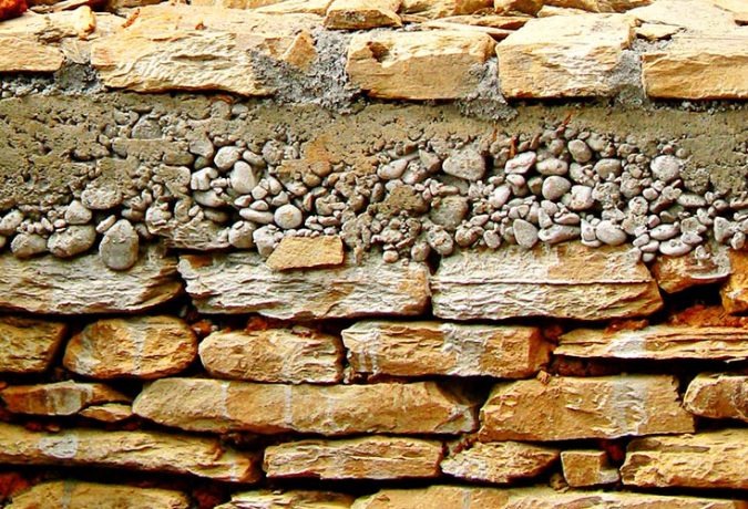
Our focus is on rubble stone masonry as it is still widely used in the Himalayan areas, which consists of field stones and mortar, which (in the case of cement mortar) is a combination of cement, sand and water. If we incorporate reinforced concrete bands into the walls, we must also add aggregates and reinforcement steel to the list of materials.
This particular research is focusing on each of these materials separately and aims to gain better understanding of the material properties of stones, cement, sand, water, aggregates and steel bars, by investigating the effects of this particular element within their combined actions into mortars, concretes or masonry.
Material: Reinforcement Steel
Steel reinforcing bars are available in many different diameters and steel qualities, however this research is focusing specifically on the steel stirrups in concrete beams, bands and stitches. In many practical construction manuals, the most recommended steel diameter for stirrups is 6mm plain steel (left picture), and the most prescribed center-to-center spacing is 150mm, although spacing up to 400mm is seen, too.
Usually, the steel quality is defined as either ribbed or plain steel, but rarely a specific denomination is mentioned such as ‘FE415’ or ‘high strength deformed’. Plain steel, however, is not always available in the markets and then ribbed or TOR steel is purchased, as seen on the right side. TOR steel is more expensive than plain steel, but perhaps it has advantages such as better anchoring or gripping, or perhaps it shows a better performance under seismic loading, that would justify the use of ribbed steel over plain steel stirrups. These parameters must all be examined and validated, which is the main aim of this assignment.
Some manuals include information on how to bend the stirrups, such as minimum lengths of the hooks, and whether stirrups should be applied in an alternating pattern. The picture above shows that the hooks are bent at 135°, whereas the manuals prefer to bend these in a 180-degree angle. The first picture on the next page, however, has bent these with an overlap and has applied them up-side-down at places. The picture next to it shows stirrups that are improperly tied to the main bars. The first task of this assignment is to find evidence in the scientific literature that covers all these practical and technical implications, such as about the optimums for the steel quality, steel diameter, spacing and construction details.
Positioning of the Stirrups
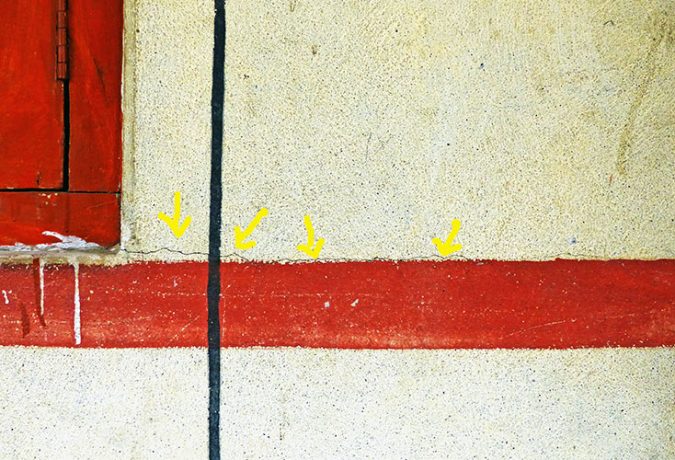
Another issue is the correct positioning of the stirrups within the bands and beams. As a general rule, the minimum cover of concrete on the steel reinforcements is 30mm. However, the majority of manuals have included detail such as shown below, where this 30mm dimension is marked from the centre of the main rod to the outside of the beam. When we have a 12mm steel bar and 6mm stirrups, the remaining measurement is only 18mm to the outside of the stirrups. This seems insufficient and may result in spalling and cracking of the concrete near the edges. This is seen in the right picture, although this negative effect is helped by the very poor execution of the concrete as well.
Furthermore, the left detail shows a very low positioning of the stirrups at the bottom of the beam. This can be avoided by placing concrete spacers under the steel reinforcements, as well as to the sides of the main bars, or maybe better, against the sides of the stirrups. This way a sufficient layer of concrete can be applied to protect the steel against water penetration. The left picture on the next page very creatively has used the stirrups to lift up the main bars.
All these question marks and critiques may look slightly overcautious and exaggerated, but too many tiny errors may cause a snowball effect and may eventually lead to failure of the beams, and worse, the collapse of the walls. Therefore, we must find ways to assess, analyze and test all these variables and variations.
Quality of CementTesting of Steel Reinforcements in Concrete Beams
I am text block. Click edit button to change this text. Lorem ipsum dolor sit amet, consectetur adipiscing elit. Ut elit tellus, luctus nec ullamcorper mattis, pulvinar dapibus leo.

